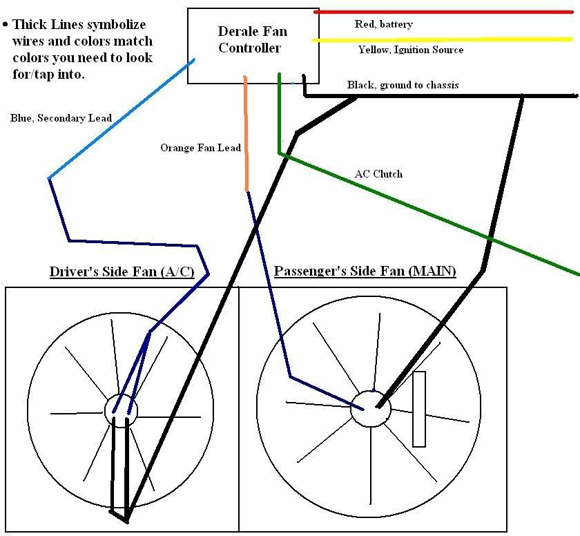
Derale Fan Controller Wiring Diagram
Diagram #4 derale perfpormance sensor override y sensor n y ion r er n s s ( ) a c u.s. Derale performance, los angeles, ca 800.421.6288 www.derale.com installation instructions adjustable electric fan controller part # 16749 kit contents qty.
The Derale Fan Controller Can Save Your Electrical Wiring! Hot Rod Network

Engine oil cooler installation kits;

Derale fan controller wiring diagram. The fan controller is working as designed. Red wire 3 #10 sheet metal screws qty. Derale performance, los angeles, ca 800.421.6288 www.derale.com installation instructions single stage electric fan thermostat part # 16735 (continues on reverse side) kit contents qty.
+12v 15amp fuse ignition power. Derale performance, los angeles, ca 800.421.6288 www.derale.com part # 16789 installation instructions adjustable dual electric fan controller kit contents qty. 18+ derale electric fan wiring diagram electric fan from www.pinterest.com.
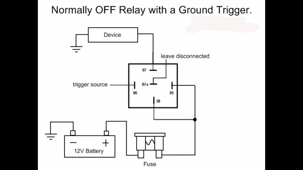
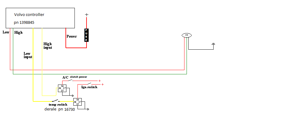
This one is a schurz.here's some similar. If you dont have the same setup as the op just add a relay for the fan circuit, prefferably a 40 amp bosch, and use the derale controller relay to activate the bosch relay coil, that way the derale control will last as it is only handling a small amount of current. Diagram #3 for manual switch wiring, refer to switch manufacturer instructions.
The extra 2 relays and double fuses solved that problem. Breaker to the red wire (harness side) located on the dual fan controller and cut the wire to the appropriate length. The electric fan assembly is built using a high output two speed motor.
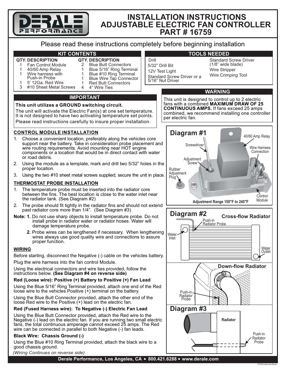
The derale high amperage adjustable dual fan controller is designed to operate two electric fans at different activating temperatures. Diagram #1 this unit utilizes an auto resetting circuit breaker to protect the fans and controller circuit. Diagram #1 this unit utilizes an auto resetting circuit breaker to protect the fans and controller circuit.
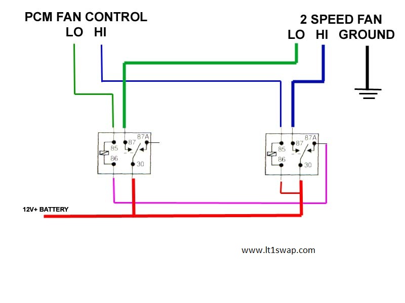
Diagram #4 fan shroud assembly rubber fan shroud seal wiring important: Diagram #4 fan shroud assembly rubber fan shroud seal wiring important: If you choose to operate the fan using both speeds, two switching devices or a derale dual fan controller part # 16788 / 16789 must be used.
Connect wire using the supplied yellow butt connector. Description 2 relay wire harness 2 40/60 amp relay tools needed wire stripper crimping tool important each relay will control up to two different fans with a combined maximum draw of 25 continuous amps. Description 2 blue butt connectors
In the event of an electrical short, the breaker Relay #2 electric fan #1 electric fan #2 87 87a 30 86 85 orange. That controller turns both fans on at the same time, the high starting load and voltage drop that goes with it kills the built in derale relay and blows the 30amp fuse when the under hood heat goes up.
Derale performance, los angeles, ca 800.421.6288 www.derale.com. The dual fan controller and cut the wire to the appropriate length. Mine lasted about 3 stop lights at 96* outside air temp.
Route the red 10 wire now connected to the auxiliary side of the circuit breaker to the positive (+) battery. If you wire the derale ground circuit to the oe relay coil ground as i described, it will prolong the life of the controller. Filmed this while filming my last vlog and wanted to do a dedicated diy on how to wire an electronic fan controller.
Disregard, cut any exposed copper and tape or shrink wrap the end of the wire. If you choose to operate the fan using both speeds, two switching devices or a derale dual fan controller part # 16788 / 16789 must be used. This should turn the fan(s) on immediately.
, using a blue butt connector provided attach the orange wire to the positive (+) electric fan lead. Route the red 10 wire now connected to the auxiliary side of the circuit breaker to. Breaker to the red wire (harness side) located on the dual fan controller and cut the wire to the appropriate length.
This single stage electric fan thermostat will control up to two different fans with acombined maximum draw In the event of an electrical short, the breaker will "trip" and open the connection between the battery and the. This newly redesigned adjustable electric fan control kit is designed to activate up to 2 fans with a total maximum draw of 25 amps.
Derale performance, los angeles, ca 800.421.6288 www.derale.com part # 16789 installation instructions adjustable dual electric fan controller kit contents qty. Reference diagrams #7 & 8 on page 3 the electric fan assembly is built using a high output two speed motor.
Derale Relay Wiring Diagram
The Derale Fan Controller Can Save Your Electrical Wiring! Hot Rod Network


Derale Fan Controller Wiring Diagram 23
DERALE High Amperage Adjustable Dual Electric Fan Controller, Push In Probe eBay

The Derale Fan Controller Can Save Your Electrical Wiring! Hot Rod Network

How to hook up a Derale Fan Controller 3000GT/Stealth International Message Center
fan controller question For A Bodies Only Mopar Forum

The Derale Fan Controller Can Save Your Electrical Wiring! Hot Rod Network
Derale 16925 fan wiring? LS1TECH Camaro and Firebird Forum Discussion
Derale 16925 fan wiring? LS1TECH
The Derale Fan Controller Can Save Your Electrical Wiring! Hot Rod Network
Ac Relay Wiring

Derale Fan Controller Wiring Diagram 23
Electric Fan Controller

The Derale Fan Controller Can Save Your Electrical Wiring! Hot Rod Network
The Derale Fan Controller Can Save Your Electrical Wiring! Hot Rod Network

Taurus fan Which temp control switch? IH8MUD Forum


Derale controller Wiring diagram for installing a Derale f… Flickr

Derale Fan Controller Wiring Diagram 23